Choosing the right Cylindrical Gear Motor begins with the machine’s real operating conditions, not its catalog rating. Load size, speed, duty cycle, installation space, and starting torque must work together. A motor that looks powerful on paper may still overheat beside a conveyor running twelve hours daily.
Dr. Hermann J. Stadtfeld, a respected gear-design specialist, offers a useful principle: “Gear performance depends on the complete transmission system, not on tooth geometry alone.” This idea applies directly to Cylindrical Gear Motor selection. Buyers should examine the gearbox ratio, rated torque, service factor, shaft arrangement, lubrication method, and motor efficiency. Check the details.
Imagine a packaging line with frequent stops, dusty surroundings, and a heavy belt. Its motor may need higher starting torque, stronger bearings, and suitable protection against contamination. A clean laboratory mixer may require quieter operation and precise speed control instead. The application changes the answer.
Experience also reveals an uncomfortable truth. Many selection mistakes come from using average load data. Real machines rarely behave perfectly. Sudden jams, uneven products, poor alignment, and voltage variation can shorten service life. I have seen specifications appear adequate until the first demanding production shift.
This guide explains how to compare torque, speed, efficiency, mounting options, noise, maintenance needs, and supplier support. It also considers overlooked factors, including ambient temperature and emergency stopping. The ideal Cylindrical Gear Motor is not always the largest or most expensive option. It is the one that performs reliably under actual conditions. That requires careful questions, honest measurements, and occasional reconsideration.
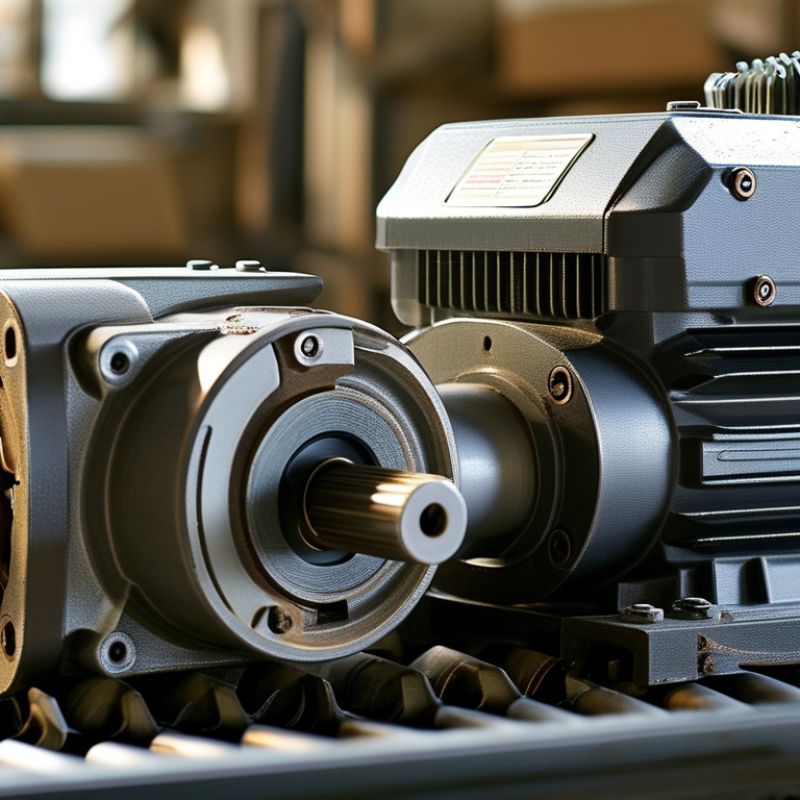
Choosing the right cylindrical gear motor starts with application facts, not catalog size. Define required output speed in revolutions per minute at the driven shaft. A conveyor moving 0.4 meters per second may need only 60 rpm. Measure it. Required torque must include startup resistance, friction, and the heaviest load. Use a safety margin, but avoid doubling everything without evidence. Oversizing can waste energy and reduce control quality. It happens often.
Duty cycle describes how long the motor runs, stops, and repeats. Record operating minutes per hour, starts per minute, and ambient temperature. Intermittent motion can create higher thermal stress than steady operation. A motor rated for continuous service may still struggle with frequent starts and repeated peak torque. Check gearbox thermal limits, shaft loading, and permissible radial force. These details matter. In dusty or humid areas, enclosure protection and ventilation deserve practical attention. A clean test bench can hide harsh field conditions.
Load type also changes the selection. Constant loads, such as rollers, differ from shock loads from indexing tables or reversing mechanisms. For lifting systems, calculate shaft torque and consider holding requirements during power loss. For pumps and fans, speed behavior may matter more than starting torque. Verify measurements after installation, because estimates can miss belt tension, misalignment, or product jams. I would rather review one week of operating data than trust a perfect spreadsheet. Selection remains iterative, and that is not a weakness.
| Application Example | Required Output Speed | Typical Torque Range | Duty Cycle | Load Type | Key Selection Considerations | Suitable Gear Motor Characteristics |
|---|---|---|---|---|---|---|
| Small Conveyor | 20–120 rpm | 5–30 N·m | Continuous operation, up to 24 hours/day | Steady, moderate radial load with low to moderate starting resistance | Calculate torque at start-up and during acceleration. Check belt tension, pulley diameter, and required line speed. | High-efficiency helical gearing, continuous-rated motor, suitable thermal capacity, and adequate output-shaft radial-load rating. |
| Packaging Conveyor or Indexing Line | 10–80 rpm | 10–60 N·m | Intermittent operation with frequent starts and stops | Variable load with repeated acceleration and deceleration | Allow for acceleration torque and peak current. Confirm the permissible starts per hour and brake or control requirements. | Low-backlash gearing, strong thermal performance, compatible motor control, and optional holding brake where position must be maintained. |
| Rotary Table | 1–20 rpm | 20–150 N·m | Intermittent, cyclic positioning | High starting torque, occasional shock, and momentary overhung load | Determine inertia, indexing time, stopping accuracy, and the maximum moment load on the output shaft. | High reduction ratio, low backlash, rigid housing, high peak-torque capability, and a brake or servo-compatible motor when accurate positioning is required. |
| Mixer or Agitator | 30–300 rpm | 30–250 N·m | Continuous or extended operation | Steady load that may increase significantly at start-up or with changing material viscosity | Use the highest expected viscosity and material level for sizing. Consider start-up torque, sealing, and heat dissipation. | High service factor, robust helical or helical-bevel transmission, sealed construction, and sufficient low-speed torque. |
| Screw Feeder | 5–60 rpm | 25–200 N·m | Continuous or frequent cyclic operation | High breakaway torque, uneven bulk-material resistance, and possible shock loading | Size for a jam or compacted-material condition when applicable. Verify the axial and radial loads transferred to the output shaft. | High service factor, overload tolerance, strong output bearings, and a torque limiter or overload protection for blockage conditions. |
| Lift, Hoist, or Vertical Actuator | 5–50 rpm | 20–180 N·m | Intermittent lifting with defined rest periods | High static load, reversing torque, and potential load back-driving | Calculate lifting torque from load, drum radius, and mechanical efficiency. Evaluate stopping distance, holding requirements, and failure protection. | Motor brake, rated holding torque, appropriate service factor, controlled acceleration, and a secondary safety measure where personnel safety is involved. |
| Automatic Door or Gate Mechanism | 5–40 rpm | 5–50 N·m | Short cycles with frequent daily operation | Reversing load with variable friction and end-stop impact risk | Check opening and closing time, inertia, travel limits, noise level, and the number of cycles per day. | Quiet helical gearing, compact design, controlled ramping, position feedback compatibility, and an integrated or external brake when needed. |
| Roller Conveyor | 30–200 rpm | 3–25 N·m | Continuous or start-stop operation | Distributed load with moderate friction and occasional product accumulation | Account for the total conveyed mass, roller diameter, incline, friction, and the possibility of product accumulation. | Compact cylindrical housing, efficient gearing, adequate radial-load capacity, and motor control suited to frequent starts. |
| Inspection or Metering Equipment | 1–100 rpm | 1–20 N·m | Intermittent, precision-oriented cycles | Low to moderate load with strict speed consistency | Prioritize repeatability, backlash, vibration, noise, and speed regulation rather than maximum torque alone. | Low-backlash transmission, stable motor speed, low vibration, encoder compatibility, and a brake if the mechanism must hold position. |
Selection note: The values shown are typical preliminary design ranges, not final sizing data. Confirm required torque using the actual load, acceleration, friction, transmission efficiency, shaft geometry, ambient temperature, and safety factor. Motor power can be estimated from P = T × n / 9550, where P is in kilowatts, T is torque in newton-metres, and n is speed in revolutions per minute.
Measure output speed, required torque, duty cycle, load type, and ambient temperature. Use machine data, not catalog size alone.
Include startup resistance, friction, the heaviest load, and shaft losses. Add a sensible safety margin. Do not double everything automatically.
Record running minutes per hour, starts per minute, and stopping periods. Frequent starts can create more heat than steady operation. This is easy to underestimate.
Constant roller loads differ from shock loads during indexing or reversing. Lifting systems may also need holding torque during power loss.
Yes. Repeated starts and peak torque can exceed gearbox thermal limits. Check temperature rise, cooling conditions, and shaft loading.
Confirm suitable enclosure protection and practical ventilation. An IP rating covers dust and water entry, not chemical resistance. A clean test bench can mislead you.
Listen during startup, steady running, and load changes. Unusual whining may suggest misalignment, damaged teeth, or excessive backlash. Listen closely.
It helps compare tooth bending stress and pitting resistance with real service conditions. Include shock loads, operating hours, and the actual service factor.
Yes. Measure casing temperature, noise, speed, and load behavior for at least one operating week. Belts, jams, and alignment can change the result.
No. Excessive oversizing can waste energy, increase cost, and reduce control quality. My first estimate may be wrong, so I would review the field data.
Choosing the right Cylindrical Gear Motor begins with a clear understanding of the application. Define the required output speed, torque, duty cycle, and load type, including whether the load is constant, variable, shock-prone, or subject to frequent starts and stops. Calculate the operating torque and apply a service factor of approximately 1.2–1.5 to allow for startup loads, uncertainties, and long-term reliability. Then select a suitable gear ratio and output speed while considering the cylindrical gear arrangement, mounting orientation, and available space.
Efficiency and durability are equally important. Compare motor efficiency according to IEC 60034-30-1 classes, such as IE2, IE3, and IE4, while balancing energy savings with purchase cost and operating conditions. Before final selection, verify the thermal rating, expected noise level, IP protection rating, and gear strength in accordance with ISO 6336 principles. A properly matched motor should deliver the required performance without overheating, excessive wear, or unnecessary energy consumption.

 Syncdrive Motor